Special Projects: Making a Decorative Railing Pt. 2

This is an ongoing series of blog posts that will showcase the design, construction and installation of a decorative steel veranda railing for our Benjamin Street project. To read the previous post in this series, click the link here or go to the main blog page.

So we have our design; we have all of our original and necessary new pieces; we have our equipment ready. Now it’s time to begin the deconstruction of the segments we are repurposing in coordination with our design plans.

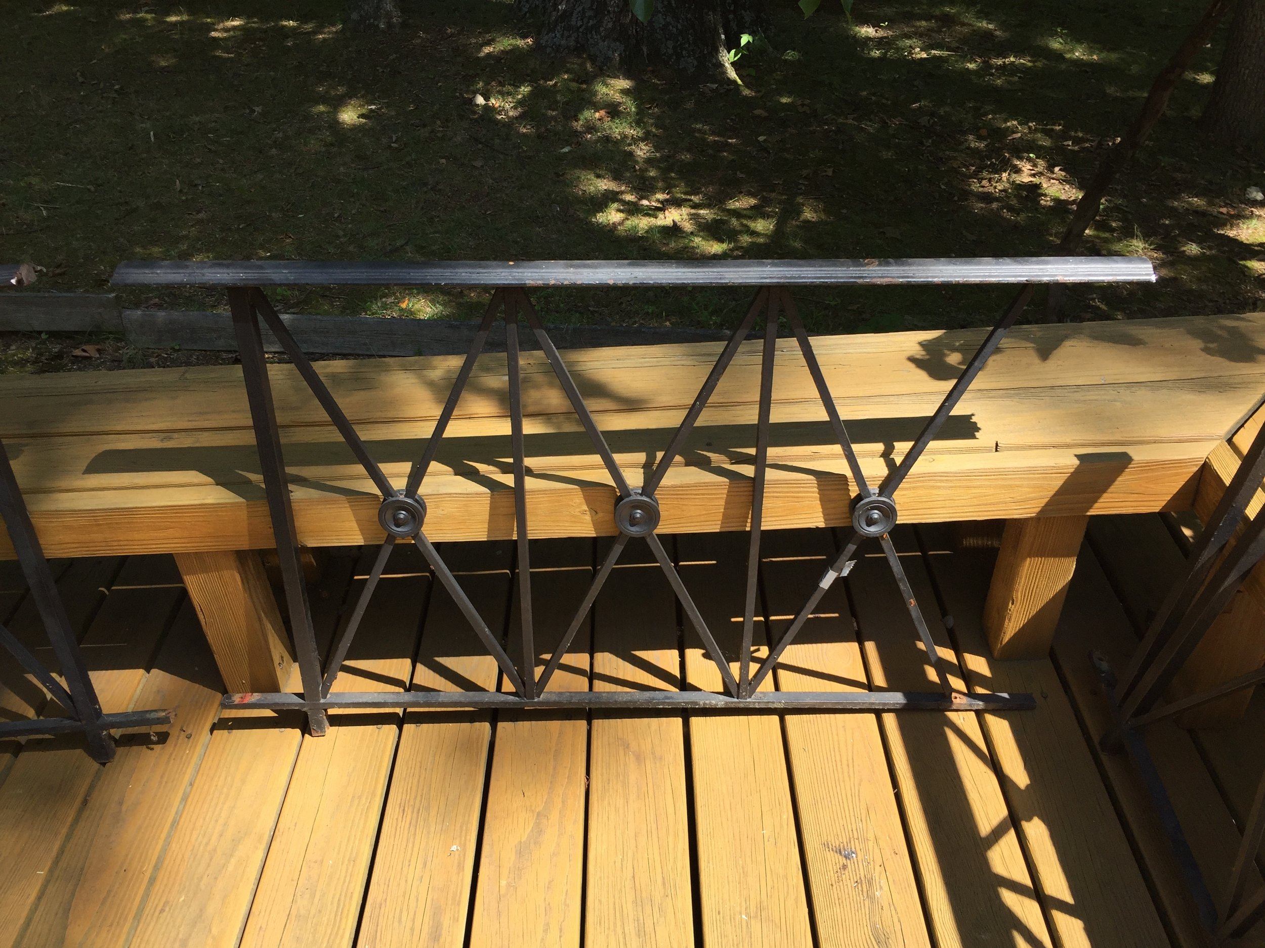
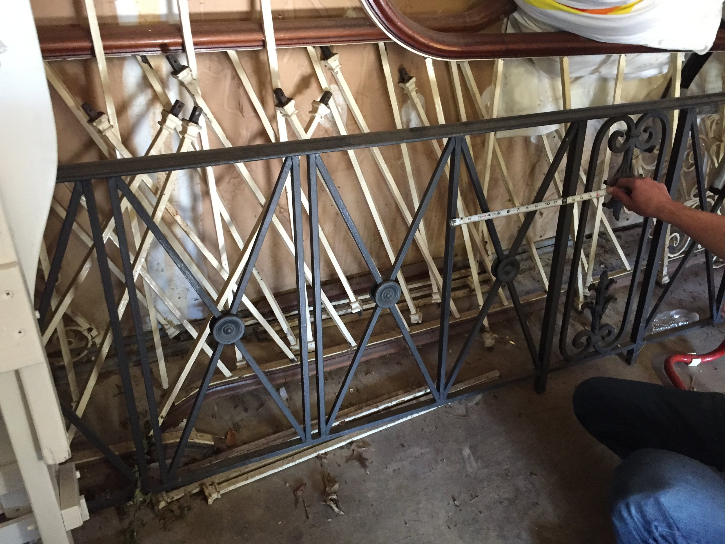
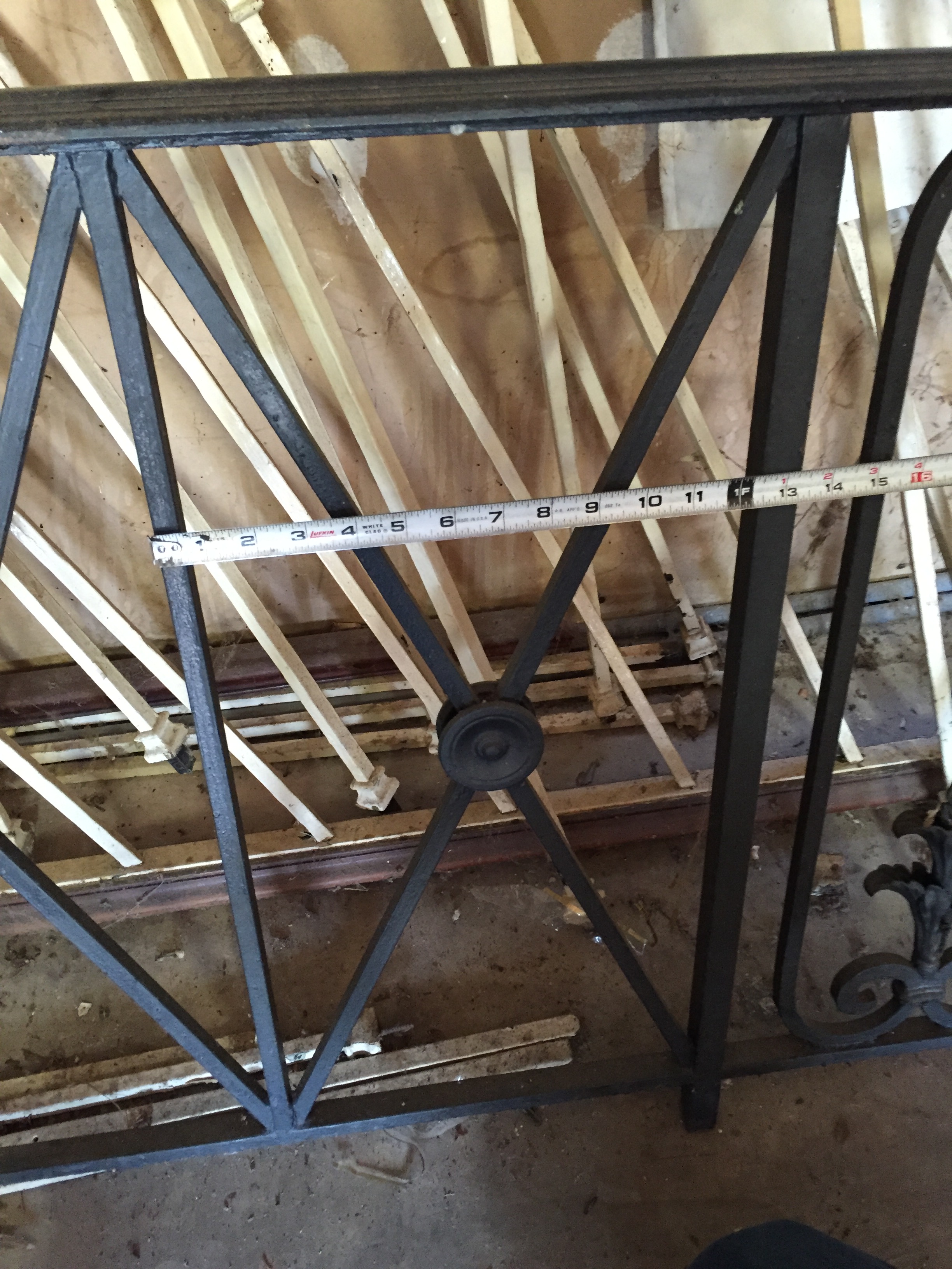
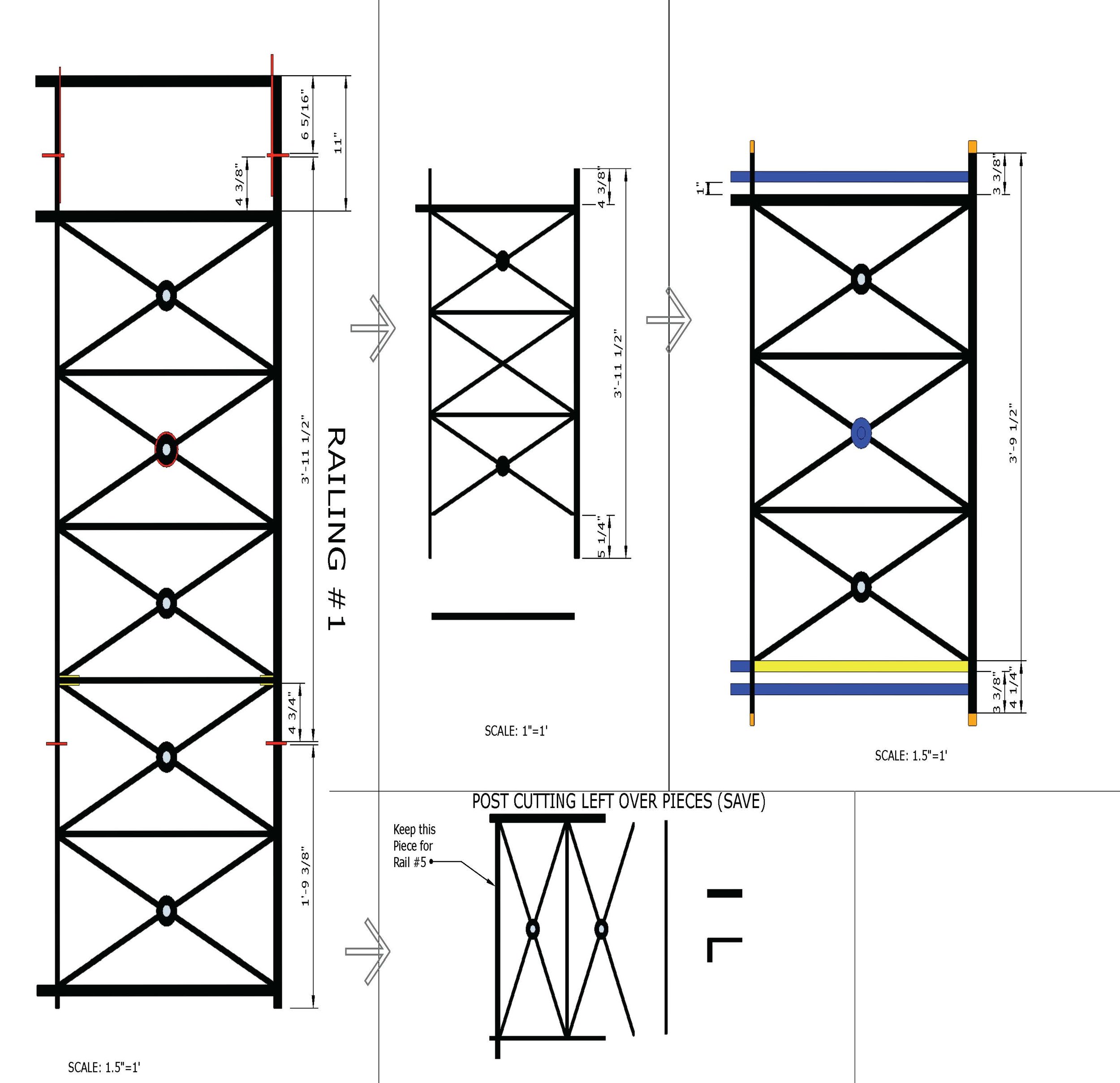
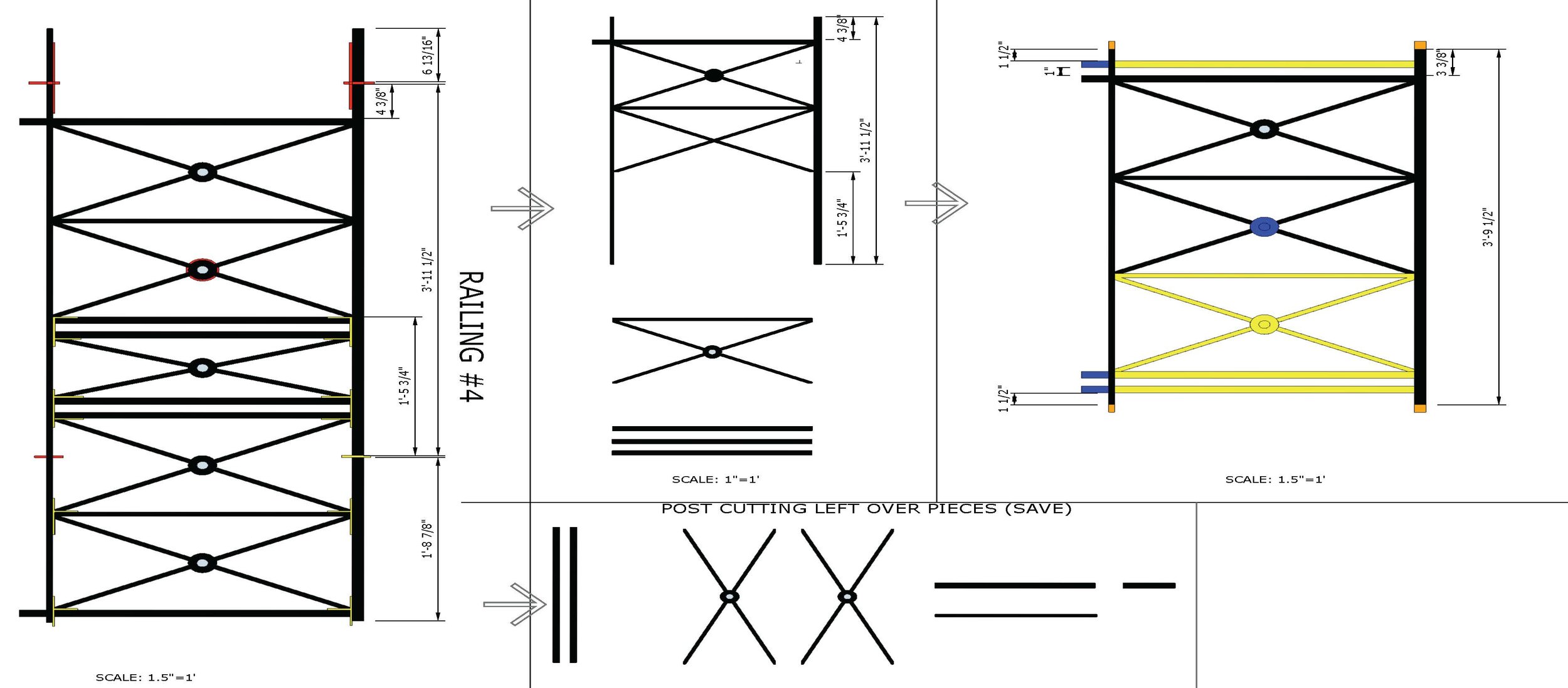
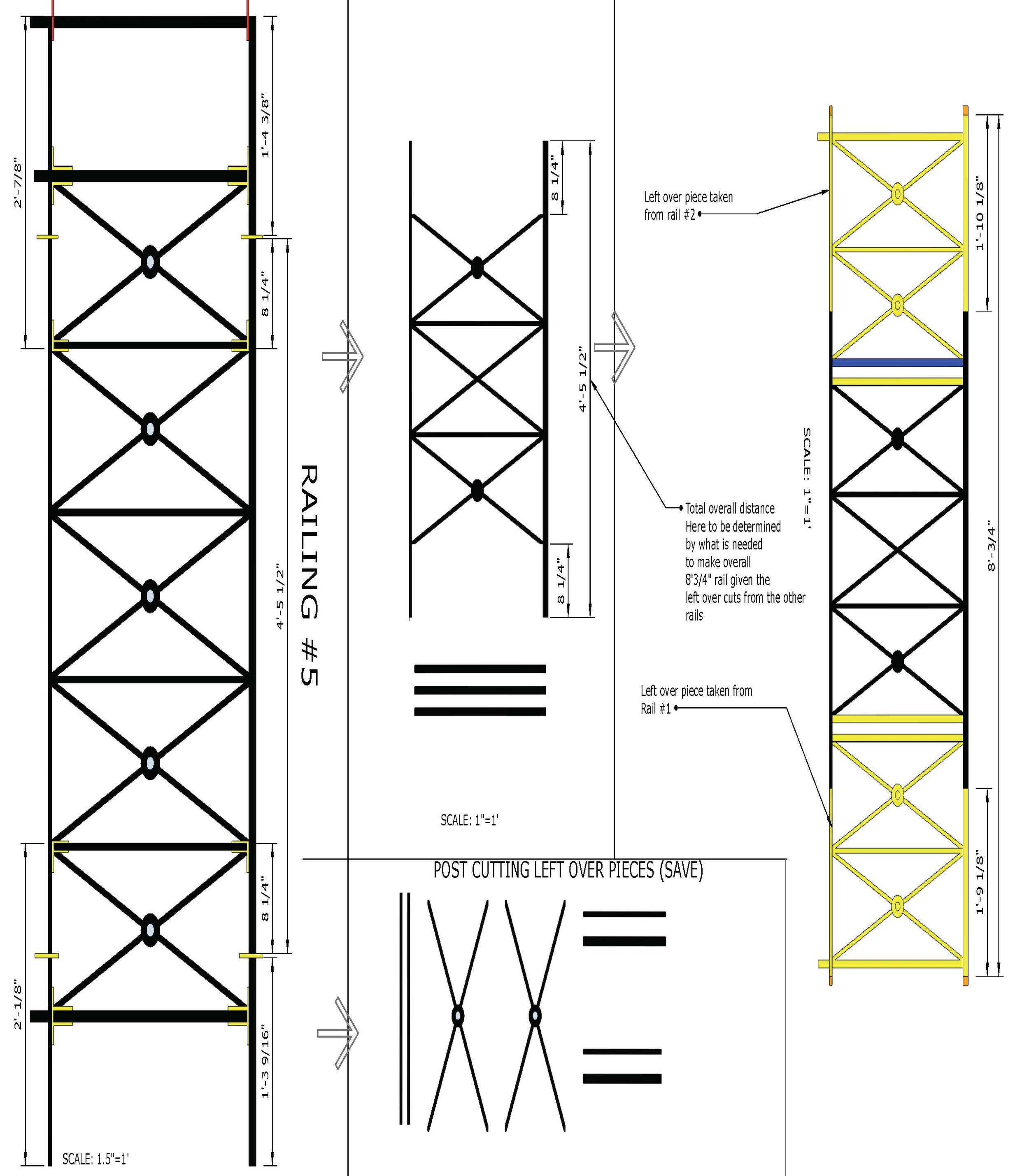
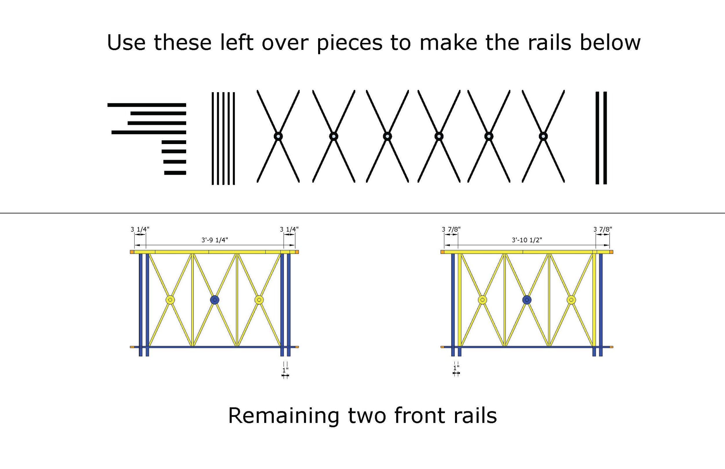
We showed you our intentions as to what pieces needed to be removed as we cut the rail into smaller sections and now it’s time to test the preliminary big segment cuts. For example, look at layout for ‘Railing #3’ and its different color-coded pieces.

Screen Shot 2017-05-15 at 11.18.36 AM.jpg

These indicate a variety of things: the red lines indicate the initial cuts needed on the existing pieces; the yellow color indicates that a specific piece removed from another section will be inserted in that given location and the blue color means an insertion of a new piece of steel that we ordered and had on hand to replicate the missing necessary features.

On Railing #3 we needed one 1” square vertical bar from another rail as well several pieces from our pile of new steel.  The new pieces needed were two 1” square vertical rails, three 1” square footer pieces and two decorative rosettes that we would weld on each side, replacing the previous rosettes that were no longer on the center-most rail section.

The new rosettes we found were from King Architectural Metals and fit our ideal size as well as a similar aesthetic to the old ones. It had an open hole in the center, which would allow us to weld it down properly, overtop of the previous center spoke from which we had removed the original rosette.

2016-08-26 12.21.35.jpg

Each rail segment followed the same procedures based on our design. Using a Sawzall reciprocating saw with a specific steel cutting blade, the dismantling began and segments became lighter and more in-line with the end product.

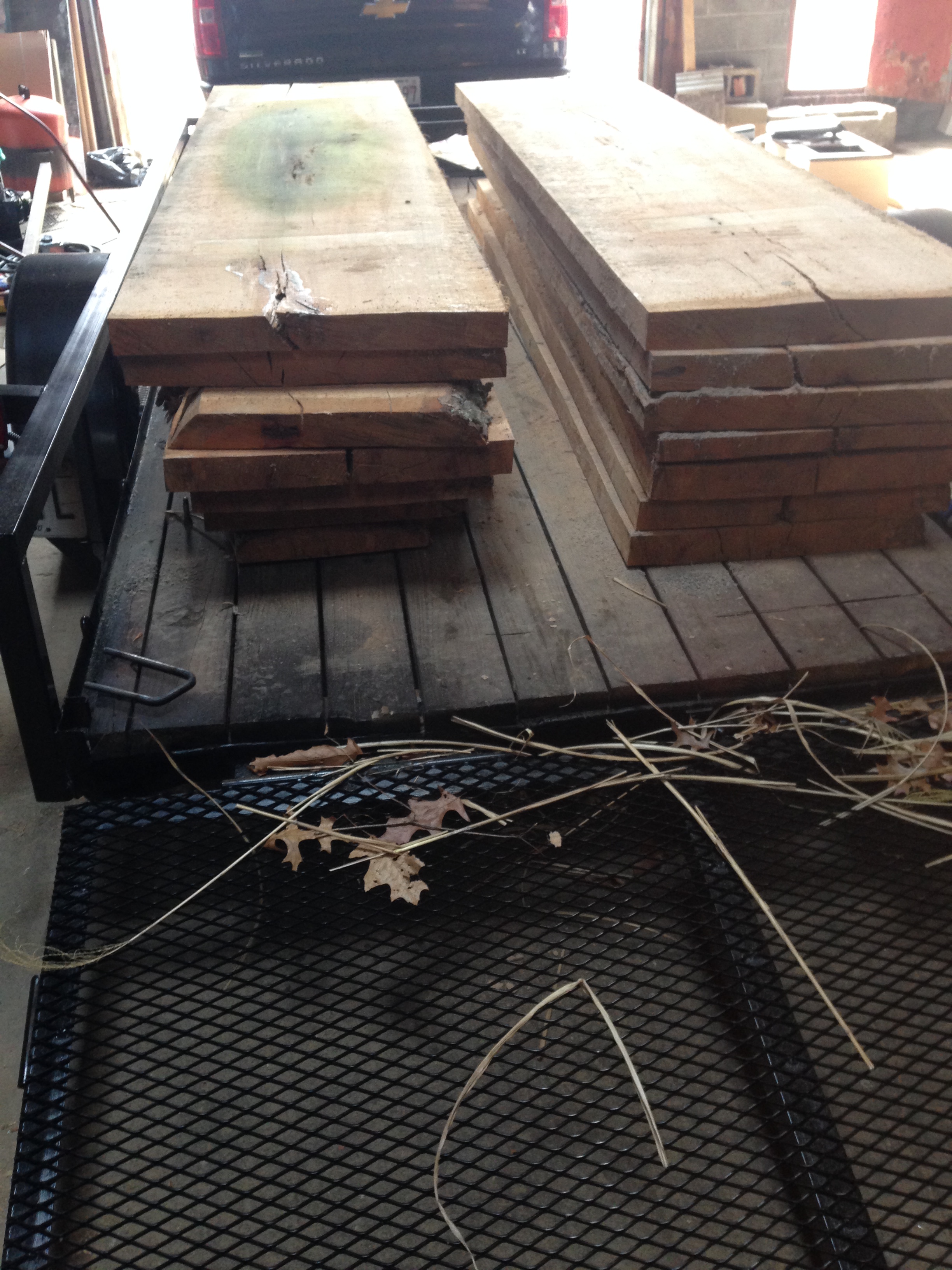
Once a given segment had been cut at the red cut points and the removed pieces were set aside, they were laid out on the back deck of our workshop. One by one, the segments were cut down and our pile of leftover parts grew. You can see the progress in the pictures that show the rails prior to any additions.

Each section was meticulously labeled to ensure that each section was true to size based on our original measurements we took from the veranda and the placement of the dividing posts. When all seven rail segments were completely cut down, it was time to divide up pieces from the extra pile.

The next step before welding the existing pieces down was to cut the remaining bars needed from our pile of new steel. We cut the steel based on our overall layout design, leaving a little extra on the ends since cutting the steel a little too long is better than cutting it too short.

Once we had all the necessary bars and rails cut to size, we started tack welding the pieces in place. Tack welding is the process of using small weld points to keep something in the proper location and alignment before final welding can be completed to truly lock the steel in place.

Once a segment had all of its pieces in place, I went around all the seams and gave it a solid final weld. 

After the segment had cooled down from the welding, each one had to be grinded and smoothed down using an electric hand grinder with a special metal cutting disc to remove any steel splatter and rough welds.

The final items to be welded were the aforementioned decorative rosettes. They are made of a very thin bit of steel, making them very delicate to weld down without melting them, which is why I saved them for last.

Now that all of the welding on a given section was complete, it was time to give them a few coats of black Rustoleum exterior paint to lock the steel away from moisture and possible future rusting. This entire process was done for each segment: cutting, dividing, adding, welding and painting.

All seven segments followed this process in a lengthy and somewhat aggravating process. By the time the segments were completed, I had earned several minor scars from burns and an achy back from moving these heavy steel rails.

While the whole progression of the rails was tedious, seeing each of the final products leaned against the wall ready for installation was extremely gratifying.

Check back for the final post in this series to see how the rails turned out once we began the installation process on the porch veranda roof.

Benjamin Exterior: Renderings vs. Reality

Our Benjamin property is now officially on the market. Last week we showed you our kitchen designers 3D renderings compared to the the true end result that you can see here.  Now that Spring has sprung, our landscaping now more resembles the renderings that our landscape architects at McHale Landscape Design in McLean, VA designed. 

Here's a few side-by-side comparisons showing the projected landscape and our end result that you can see in person now.

BlackRock Update: Gordon

Our home at 6636 Gordon Avenue in Falls Church is underway with our completion date nearing. While we still are a few weeks out, here's a quick look at the progress of the house compared to the original design we made prior to starting construction. 

We'll make sure to update you on its progress as well as once it hits the market. If this home, or any of our other homes are of interest to you, please reach out at 703-734-1091 or email us at info@blkrk.com

Smart Homes: Samsung SmartThings

This is an ongoing series of blog posts that will explore the world of smart home technology and home automation by explaining the variety of facets currently on the market, paired with our personal experience as we test the products out to further both your and our understanding. To read the other posts in this series, click the ‘Smart Home’ category on the main blog page. 

Now that you’ve been given the basics of home automation and smart home equipment, it’s time to delve into some specific technologies that serve as a bridge or gateway to other smart products. One of the most prominent companies in this field is Samsung’s SmartThings division that provides easy access through the SmartThings Hub, which has an ever-growing list of compatible devices from other manufacturers. 

The aforementioned SmartThings Hub is basically the brain and heart of the system. The hub is required for connecting any other SmartThings product, but not exclusively necessary for connecting non-Samsung products. All your Amazon Alexa products we’ve touched upon are compatible via voice control when your SmartThings and Alexa apps are connected.

Some of the third-party products that can be routed through the SmartThings Hub include: Amazon Echo and Google Home voice assistants, Netgear and Ring cameras/video doorbells, Schlage and Kwikset smart door locks, ecobee and Honeywell thermostats, Leviton and GE outlets, Bose speaker systems, Aeon Labs and Ecolinks sensors, and a slew of smart lighting including Philips Hue, Cree, Sylvania, Lutron and Belkin.

Take a look at this link for a full list of what Samsung SmartThings can integrate.

Samsung sells a pretty convenient bundle of its various smart devices. While it still remains a bit pricey, the prices have started to come down as other companies expand their electronics into the smart home category.

The various pieces the bundle includes are the hub, a motion sensor, smart outlet and two multipurpose sensors. Additional SmartThings products on the market include water leak sensors and arrival sensors.

A majority of these products are self-explanatory, but others can be used for multiple purposes:

  • SmartThings Hub: As explained above, the hub is required for all other SmartThing devices. The hub connects via Ethernet to your Internet source and when recognized by the SmartThings app is able to give you a full readout on all your devices, its battery levels and temperatures throughout.
  • SmartThings Motion Sensor: When connected with other third-party products, the motion sensor can connect to home security cameras to alert you with unauthorized movement in your home as well as begin recording video when coupled with a smart camera.
  • SmartThings Smart Outlet: This is exactly what it sounds like; plug this into any typical wall outlet and then plug a household electronic into the outlet and you are now able to remotely turn the outlet on or off using the SmartThings app. Perfect for small kitchen appliances or non-smart lighting.
  • SmartThings Multipurpose Sensors: These also have a few different uses for smart home monitoring. When installed, these sensors allow you to tell if your doors or windows are open or closed as well as cabinets and drawers. While you aren’t able to remotely close them, you can be alerted if one of the sensors changes while away from home. The multipurpose sensor also detects temperature in any given location.
  • SmartThings Water Leak Sensor: With another obvious name, the water leak sensor allows you to monitor locations affected by moisture. Ideal places include under a sink, near a bathtub and even in your basement if you have flooding/seepage concerns.
  • SmartThings Arrival Sensor: These are simply a key fob you can attach with your house keys or throw in a purse or backpack. The arrival sensor allows you to program your smart lighting to turn on when within a certain radius or turn off when outside that radius. 

With a better general understanding of Samsung SmartThings, you are now more equipped to determine what sort of technology is right for you.

Some people are only interested in home security, while others are more focused on automation and efficiency.

Once you identify what route you want to take you can begin to research specific products that are best for your purpose.

Personally, I prefer the multipurpose sensors that give me the piece of mind that my doors and windows are closed in my apartment as well as the motion detector that I have connected with a pet camera to monitor my dog.

Next post in this series will begin to touch upon the various external third-party items you can connect through the SmartThing Hub, beginning with smart lighting.

If you have any questions on home automation or SmartThings specifically, as always, feel free to reach out.


415 M Street: Historic Corbel Design Part 1

At BlackRock Holdings we typically demolish the buildings we buy to make room for a new custom home, but this isn’t the case for our Washington, D.C. property at 415 M Street NW that we intend on turning into six luxury condos.

D.C. has very rigid historic property policies that restrict builders from drastically changing the look and feel of existing buildings.

This primarily effects existing structures rather than new buildings, however new construction typically has to adhere to some historic policies so it visually fits in with the neighborhood.

415 M Street has a lengthy history behind it that you can read here or watch a video about it here.

The synagogue mural formerly in 415 M St.

The synagogue mural formerly in 415 M St.

The Historical Society of Washington, D.C. had to come out to the building site and advise us as to what can and cannot be altered as well as what needed to be replicated or at the very least similar to what was previously in its place.

The primary rules the Historical Society passed down to us was that the existing brick exterior walls had to remain in place.

(Side Note: During the preconstruction process, the Jewish Historical Society of Greater Washington reached out to us regarding a mural on one of the walls inside the building. In the rich history of 415 M Street, the building was at one point a synagogue and contained some Jewish artwork painted on the interior walls. A fundraising effort was setup to preserve and remove the mural intact, which was successful and now resides in the hands of the JHSGW.)

While initially this may not seem like that big of a deal, for a builder, this means that extreme care has to take place during the entire construction process. We had to brace all of the walls to refrain from collapsing before we could even begin the gutting of the interior. Of the four walls, the front façade is the most important since it faces the street, so that means other exterior features must also remain.

The key exterior feature to the front of the building is the window headers and the decorative roof trim. The focal point of the roof trim is four large corbels spaced evenly from corner to corner. A corbel is defined as a projection jutting out from a wall to support a structure above it or a support for a structure such as an arch or balcony.

As you can see from the zoomed in photo of the 415 M Street exterior, the corbels on the building are more decorative than structural. These corbels contain an elegant design from the early 20th century and were something that we would either have to refurbish or replace with a similar version.

So this was the inception of a new special project to be completed: a corbel rebuild for 415 M Street NW, which would mean dissecting the original versions and building the new replica model.

This ongoing blog series will document the corbel building process beginning with the initial redesign using 3D design software and will cover all of the steps as we recreate a piece of 100+ year history that will last for at least another hundred years.

So stay tuned to the BlackRock blog or Facebook page and if you have any questions, feel free to reach out.

Benjamin's Kitchen: Renderings vs. Reality

Now that our Benjamin property is primed to hit the market, we thought it would be cool to show you the end result in comparison to what our kitchen designers at Lobkovich Kitchen Designs had rendered in their program. 

As you can see from the above rendering compared to the photo, the only differences between the images is a variation of the lighting fixtures and kitchen island chairs as well as the style of the range hood. It's almost like the 'Can you spot the differences between the photos?' kids game, except with high-end interior design brilliance. 

BENJAMINKITCH.jpg

Join us for the Northern Virginia Parade of Homes this weekend!

This weekend is the annual Parade of Homes presented by the Northern Virginia Building Association (NVBIA). Parade of Homes is described as "the area's finest builders and developers showcasing their innovative ideas, special design features, dynamic floor plans and master craftsmanship" and runs this weekend, Saturday, April 29th and Sunday, April 30th from 11AM-5PM.

Our newest construction is a six bedroom, six full bathroom and two half bathroom luxury home at 7109 Benjamin Street in McLean, VA and will be a part of the parade , which can be accessed all weekend. While this home doesn't hit the market on the MLS until next week, those interested can get a pre-listing view of this 10,000+ sq.ft. beautiful blend of American Classical and Georgian construction on a one acre lot.

If you're interested in seeing this home outside of the Parade of Homes hours, feel free to call our office at 703-734-1091 or email us at info@blkrk.com and we'll find something that works for you. Take a look at the photo gallery below of the home, but this home is definitely one you must see in person to get the full experience of this truly custom home. 


Smart Homes: Exploring the basics & other smart products

This is an ongoing series of blog posts that will explore the world of smart home technology and home automation by explaining the variety of facets currently on the market, paired with our personal experience as we test the products out to further both your and our understanding. To read the other posts in this series, click the ‘Smart Home’ category on the main blog page.

In my first post regarding home automation I talked about the new mainstream leader on the market, which is the Amazon Echo. I went into some detail as to what the Echo itself is capable of, but it’s the numerous third-party app integrations that truly make it shine.

The Echo has an entire ‘Smart Home’ section coupled with the ‘Alexa Skills,’ which is the method in which you are able to connect your other various home automation and smart products. The Skills section can be accessed in the Alexa app main navigation as well as on Amazon’s website. While the Skills library is still somewhat small, it’s constantly being updated with new features and companies that have developed ways to enable their devices via the Echo.

Skills must be enabled for them to be used via voice recognition, but a majority of them also require connecting other accounts to the Alexa app. Commands like “Alexa, play Jeopardy” or “Alexa, play the Joe Rogan Experience” are examples of non-connected skills that only require you to click ‘enable skill’ and you’re able to enjoy immediately.

Personally, I have the Fandango skill that allows me to check movie times, the Yahoo Fantasy skill that allows me to hear my Fantasy Football scores, the TrackR skill that allows me to locate my phone if it’s lost in my apartment somewhere and even the Dog Facts skill that will tell me random information about dogs if asked.

Clearly some of these skills are very insignificant, but are entirely customizable for you, the consumer. I must express though that using TrackR to find your phone lost in a couch cushion is extremely handy, but none of these are truly smart home specific.

The minor skills that your Echo can learn seem endless and you can get lost scrolling through the skill library. Within minutes you’ll have your Echo customized and working way beyond its original software.

The more personal applications like connecting your smart thermostats, security cameras or light bulbs all require you to give permission through Alexa by logging into that account and allowing the two accounts to be joined. These are a few of the prominent examples of smart home integration that currently exist.

However, these are a small fraction of what’s available. A good amount of the smart home skills are extremely similar, just developer-specific dependent upon which company you’ve decided to use in your smart home.

In later posts I will delve into the specifics of each type of smart home facets and skills, specifically regarding ones that I’ve personally tested and used as well as a few honorable mentions of ones that have similar features. I named a few of the smart home skills earlier in the post, but the current full array of products that can be controlled is much more extensive.

A smart home can include lighting and switches, home climate and thermostat control, security cameras and alarms, electrical outlets, door locks and garage openers, television components, kitchen and laundry appliances, smoke detectors, sprinkler and garden watering systems and a multitude of sensors that monitor motion, water leaks, open doors and even when a family member returns home, all entirely wirelessly controlled.

Some of the main manufacturers in the smart home industry include Philips Hue, Cree, TP Link, Nest, Ecobee, Logitech, Belkin, Luma, Zigbee, WeMo, zWave and many more are popping up every week.

The above referenced smart home skills may seem complicated, but in reality the setup and connections couldn’t be any simpler. Many of them require a separate app and account through the specific company that is then routed either straight into the Alexa app or into a more generalized smart hub such as Samsung’s SmartThings.

The next post in this series will explore Samsung’s SmartThings Hub and its various add-ons that we use in the BlackRock office as well as in my apartment. The hub is a piece of equipment that has some equivalent counterparts made through other companies, but Samsung is the current leader when it comes to the smart home game, whether you’re shopping online or in-store. Just take a look at Home Depot’s main Home Automation Basics site.

We look forward to bringing you more smart home information and as always, if you have any questions or comments, feel free to email me.

Special Projects: From Tree to Table Pt. 2

This is the second post in our ‘From Tree to Table’ series. If you missed the first blog post, take a look here and then come back and read the follow-up.

In the previous installment we explained the initial process of cutting the tree down into slabs on-site, air and kiln drying time and then planing the wood. This is the standard method of getting any wood carpentry-ready and is a process that we repeated on a red cedar tree at our Weaver Avenue property.

The red oak was the first one that I got to be involved in and you can see plenty of pictures of the process. The red cedar was substantially lighter than the red oak and had a familiar smell of hamster cage shavings, except it smelled clean.

After the cutting was completed, all of the same drying and squaring steps were repeated prior to using the wood. After the requisite six-week or so I was able to begin plotting out how I wanted my table to look.

An early table design idea that was scrapped due to the size of the cedar slabs.

An early table design idea that was scrapped due to the size of the cedar slabs.

Our construction manager, Joe Little, and I decided to build a custom wooden kitchen table for my apartment that would both compliment the interior colors and required space in my dining room. While I was completely inexperienced in any sort of ‘from scratch’ carpentry, Little had recently built himself a new dining room table from the aforementioned oak slabs and began to expound his knowledge and experience at me as we built my table.

The first step was cutting down the wood into four even rectangular pieces to the desired size we wanted of a 2’ x 5’ table. Next, we glued and clamped the pieces in place. This was actually the longest part of the building process, taking about 6 hours since we had to wait for the glue to properly adhere before we mounted it to the legs.

Once the glue dried, it was time to start mapping out the table skirt and legs. The table skirt is the band of wood below the tabletop that typically is inset below the top so it creates an even lip around the table. We used some basic 1x6 pieces of wood to build the rectangular skirt and once assembled, centered it evenly on the underside of the table and glued it into place along with some small tack nails to make sure it didn’t move while drying.

The last component of actual construction was the table legs. At first we considered using some repurposed stair rail posts for the legs, but ultimately decided they looked too skinny and moved onto making our own. Instead, we took two 1x6 pieces of wood and formed an ‘L’ for each of the legs.

Before we fastened each together, we decided to give the legs some flare rather than just being straight legs with hard right angles.  Little and I designed a basic curve that would allow the legs to transition from thick to a skinnier foot type that would rest on the floor and match the rest of the table. Once we settled on the look, we cut the same shape into all eight pieces that would compose the legs.

The ‘L’ of the legs were positioned on the inside of the table skirt’s corners, giving the table multiple shadow lines as almost a reverse pyramid type of construction and the tapered legs touching on the long end of the curve. These pieces were all attached using the same tack nails that are small enough for a nail gun to shoot in and avoid being visible in the final product.

Now that we had all of the pieces assembled came the more grueling work. While it wasn’t as bad as watching glue dry, the sanding process of the tabletop took several hours. First, the entire surface had to be sanded with heavy grit sandpaper (40 grit) on the top and sides to get any glue, sealant or other imperfections that may have been present.

We slowly worked our way up the sandpaper grit numbers to get a flatter tabletop (80 & 120 grit), but it still had some rough areas that needed to be smoothed out with the super-fine sandpaper (400 & 600 grit).

With the tabletop at an almost sleek perfection, we decided to add one more detail to the table that would give it an even more professional look—rounded edges and corners.

Since hard corners on tables inevitably end up stabbing or poking someone eventually, we took our sander and sanded in an arc motion on all four sides to round them down without removing too much of the table’s wood. Once all four sides and corners were smooth enough to run your fingers across without getting a splinter, it was time to get this table looking a bit more finished.

To match the other furniture in my dining room, I chose to paint the legs and skirt black that would offset the clear-coat stain I chose for the wood. While many may use stain colors, an advantage of clear-coat stain for red cedar is the fact that it wets the wood and then locks in the color it looks when it’s wet. As you can see from the images, the ‘wet look’ of the wood is a popping red that has no need for artificial coloring.

The clear coat took maybe an hour or so to dry and within the same day I was able to load the table onto the back of Little’s truck, take it over to my apartment and place it in its new home. While I may not have matching chairs for the table, the table itself is a brilliant color that brightens the room and astounds any visitors asking where I got it from and I slyly grin and just say “I built it with a colleague from work.”

If you have any specific questions regarding the steps or anything I may have glossed over, don’t hesitate to reach out.

Special Projects: Making a Decorative Railing Pt. 1

An early rendering of the Benjamin Street home with a white railing above the front door porch.

An early rendering of the Benjamin Street home with a white railing above the front door porch.

If you glance back at some of the Special Project blog posts, you’ll see several welding projects BlackRock has done in the past. I shared our earlier projects of rebuilding a landscaping trailer and a kitchen island, even using our homemade welding table on the latter project that was also presented in previous posts.

Now that I had some experience welding a variety of projects, I was given a new assignment that would require me to repurpose six pieces of a steel railing and turn it into smaller segments of decorative railing that would border the roof of the portico at our home on Benjamin Street.

For those unfamiliar with the term ‘portico’ like me, Dictionary.com defines it as “a structure consisting of a roof supported by columns or piers, usually attached to a building as a porch.”

Since the portico has no upstairs walkout access to serve as a real balcony, the aesthetics of the rail were the key factor rather than a functional hand railing. The portico extends above the front porch and is directly in front of the master bathroom, overlooking the front yard and driveway of the property.

Before I could get started, I had to go out to the property to get proper measurements of where each post was located on the roof so I could identify the length of each rail segment needed.  All six of the smaller segments were almost exactly evenly spaced around 3’-10” with a larger centerpiece that measured out a little larger than 8 feet.

The posts are one foot squares that setback around 1’-1” to provide a lip around the portico roof. Take a look at the floor plan layout that shows the placement to get a better visual understanding.

After getting all of the dimensions necessary, it was time to take the existing rails and get precise lengths of each portion to identify the best points to cut the rail that wouldn’t waste other pieces. After getting the numbers, I drew them in Google Sketchup exactly to scale and began to experiment separating the rails at various points to figure out what would work best.

While this process was a bit tedious, there were only so many choices to ensure that every rail matched. I took my layout that I created and inserted very basic 2D railings to show what was required of the segments.

As you can see, the original design had three full rectangles in the smaller sections with its edges dying into the posts.  Visually it looked fine, but it was not practical when it came to the cuts it would require to achieve the half ‘X’ into each post.

Taking those basics into account, I was now aware that the six small segments would fit three ‘X’ rectangles and the decorative flower portion would not be usable in the layout as the posts currently stand. Those parameters narrowed it down fairly quickly and was time to identify where each rail needed separated for our 3’-10” dimensions. 

Five out of six of the pieces were the same basic length and design, which made it a little easier in figuring out where to cut and what would be leftover.

Due to having seven openings on the portico roof, at least one of the small sides would be almost entirely fabricated out of these leftover pieces. The remaining extras would be added to build up the larger eight-foot centerpiece.

Along with the leftover pieces, extra steel was ordered that would be necessary to replicate that portions our extra pieces wouldn’t cover. I needed some more flat steel that runs across the bottom horizontally as well as more 1” square steel that makes up the thicker outer vertical pieces on the ends.

Each rectangle was about one foot, so three of them added up to three feet and we needed to fit a 3’-10” gap. The 1” square steel would be replicated to look like each piece had two runs of the thick vertical steel as shown in the gallery below.

The gallery shows some photos of the original rail as well each page of the design indicating what is to be kept, what's to be added and what's to be purchased and inserted.

Now that the theory of all of this is done, it’s time to start cutting. Check back next week to see the next step in the process. 

This blog topic will be broken into several posts to avoid confusion. Next week will feature the deconstruction of the rails as well as the process of rebuilding them. 


3D Thursday: Printing Our Own Designs

3D Thursdays are an on-going set of blog posts that dig into the world of 3D printing as we develop our knowledge and skills of the process and then present them to you to further both your understanding and ours.

An example of CAM software in ReplicatorG (image from MakerBot)

An example of CAM software in ReplicatorG (image from MakerBot)

Since we began this 3D Thursday series, we’ve explained the basics of how it works, how to print pre-made objects and what exactly slicing means in regards to the design process.  While the previous post outlined specific slicing settings, the following post will give a better overview starting with theory and ending with physical objects.

Now that we’ve covered those aspects, it’s time to expand our 3D printing knowledge. Rather than printing something via Thingiverse that someone else made, we began to design our own 3D objects in Google Sketchup. Sketchup is a similar design program to AutoCAD, except it’s significantly cheaper and much more user friendly for those who didn’t attend architecture or engineering school.

You can give the software a try with a free trial run, but if you plan on creating your own prints regularly, you’re going to need a program like this for 3D modeling. AutoCAD is generally thought of as software for creating blueprints, but also has the ability to do 3D design like Sketchup. While AutoCAD may appear cheaper looking at their respective sites, keep in mind purchasing Sketchup is a straight license, whereas AutoCAD is a subscription service that requires payment at a monthly, quarterly or yearly rate.

Once you have a design made and ready to be converted into a 3D file, it’s time to use a computer-aided manufacturing (CAM) program that converts the file types into .STL and GCode format that the 3D printer can read. There is a variety of programs that can do this, with many of them being free open-source software that anyone can download and use. These programs are mentioned in the previous slicing post, which you can view here.

We’ve mentioned Slic3r as one of these programs and we have also used ReplicatorG. We have found it very intuitive and self-explanatory. While there is a learning curve for these programs, a trial-by-error approach is best anyways since every 3D printer seems to have its own temperament and small quirks that need to be adjusted on the fly.

Now that we’re out of the explanatory portion, let’s show you some items that we designed from scratch. The first is a bracket of sorts that mounts a water pump onto our CNC machine so we can use a water-cooled spindle with our machine. The pump needed to be close to the spindle, so we made a 3D object that would allow the pump to move with the spindle, whether it was side-to-side or up and down.

The design process was fairly simple and required a few measurements of the water pump itself. We needed both the outer diameter dimensions of the pump as well as its depth to ensure the mount stuck out far enough to avoid entanglement with the Z-axis.

We also had to ensure the proper size holes were in position for the attachment to the axis and the secondary piece to connect to the main piece. Luckily the filament can be shaved down quite easily without ruining the object, so threading a screw through that is slightly too large isn’t a huge problem. The first print through proved to be slightly too small on the inside of the curve, so with some tweaking to the arc, the second print was spot-on.

The other pieces we made for our CNC machine were bracket mounts for an external cooling fan. These pieces were much easier to design and print, since they were essential just ‘L’ shaped pieces with the necessary depth for holding the fan and holes for attaching the fans existing holes to the brackets. Once again, our first print didn’t quite lineup, but a slight revision was just enough to make it work.

Lastly, we also designed a case for a piece of electronics called Raspberry Pi that we needed to install inside an old PC. The case required several specific openings to allow for cable connections of the Pi device as well as four exact holes that lined up with the PC’s motherboard to screw it in place without hurting the existing electronics. This design was one of those trial-by-error pieces that started extremely frustrating.

While we were able to get exact measurements for the Raspberry Pi itself, the more difficult measuring came to the attachment inside the computer. The screw holes took at least four prints, which we were able to stop early into the process when we noticed it wasn’t lining up. Eventually the device was both able to slip into the case as well as lineup with the screw holes, which is obviously the intended goal and end result we wanted was the computer booting up properly and all electronics starting up. Once it was all fitted in place, we were finally able to breathe a sigh of relief for completing this phase of learning 3D printing.

Our above-mentioned designs can be found on my Thingiverse account here. Feel free to download any of our personal creations or our remixed ones. If you make any of them, leave a comment or suggestions for improvement if you have any. 

Special Projects: From Tree to Table Pt. 1

Whenever we tear down a house, there are almost always a few trees that also need to come down to make room for the new house. Our arborist will first come out and determine what should and should not be removed per site plans. Once the arborist completes his assessment, we take a glance at what trees need to come down and determine if any are of unique or expensive wood quality that could be used for other projects.

So far we’ve had two properties where we found a tree we really liked the look of and wanted to utilize it in some sort of project that as yet to be determined. This was the case at one of our first houses—the Brawner model, as well as our newest house on the market at Weaver Avenue in McLean, VA.

We first inform the company conducting the tree removal that we want to keep one of the trees. Rather than loading that one onto the truck with the others, they put it aside so we could get our wood guy out to the site with his gigantic portable wood planer. This guy’s machinery slices the tree into thick wood slab segments, ideal for numerous carpentry projects. 

The first tree we did this with was a monstrous red oak at the Brawner model. Even with our wood planing guy on site, the slices of wood were all at least ten feet long and two feet wide, weighing enough that it required two people just to move a slab.

By the time he was done planing the red oak, we had 16 huge slabs that we had to load onto our trailer we made and then transport them to our warehouse. Before the wood can be used for any projects, it first has to be rid of almost all moisture. The first step in doing this is using a sealant on the ends of the slabs, which prevents the pieces from warping or cracking.

The slabs were stacked in the warehouse, separated with spacers so each slab had room to ‘breathe’ and allow for consistent airflow drying. After drying for six weeks, we loaded the slabs back onto the trailer and transported them to Hicksville Planing Mill in Clear Spring, Maryland. Hicksville is an independently owned and run Mennonite wood mill near the border of Maryland and Pennsylvania also specializing in but kiln drying and lumber sales.

The first step of the planing process was for them to put all of our slabs in their kiln to wick away the remaining moisture that air-drying wouldn’t resolve. This was another six-week period the wood would undergo before the mill could properly plane the wood.

Upon returning after the six weeks, it was time to plane the wood.  For those unfamiliar, wood planing is the process of flattening and shaping wood by creating a smooth level surface and crisp corners. One-by-one, each slab was loaded onto the large wood planer and was run through twice. The first run-through smooths the entire top with a horizontal blade to shave the uneven portions down as well as using vertical blades on both sides to do the same process to the wood’s thickness.  

The same slab is then flipped over and run-through a second time to plane the other side. After the second run, the slabs are a perfect rectangular piece of lumber ready to use. We ran all the pieces through with the help of the Hicksville workers and within an hour were completed and loaded back onto our trailer.

After we got the wood back to the warehouse and stacked it up, it was time to start theorizing what we could make from all this beautiful red oak. Take a look at the slideshow below to see the process in-action and check out the next ‘From Tree to Table’ blog post in the upcoming weeks.  


3D Thursday: Slicing settings for first time designers

3D Thursdays are an on-going set of blog posts that dig into the world of 3D printing as we develop our knowledge and skills of the process and then present them to you to further both your understanding and ours.

Once we mastered the very basics of the 3D printing process, it was time to take these steps and extrapolate them into designing and printing our own pieces. Printing pre-made items is a much simpler task when all you are doing is downloading a file and importing into your 3D slicer program, all with previously defined settings.

FIGURE #1 SCREENSHOT OF SLIC3R PROGRAM'S PRINT SETTINGS

FIGURE #1 SCREENSHOT OF SLIC3R PROGRAM'S PRINT SETTINGS

This post will focus on what exactly slicing means when it comes to 3D printing and how the changes apply when you start going off on your own.

Slicing is a term mentioned before with very little explanation. Slicing programs like Slic3r are the go-betweens to take 3D files we built in Google Sketchup and AutoCAD and turn them into .x3g files that the printer can read.

Slicing imports your design and then gives you hundreds of options as to how you want your item to print. The first steps are setting up your ideal settings with varying results exclusive to each piece printed. [SEE FIGURE 1 & 2]

FIGURE #2 OF SLIC3R PROGRAM'S PRINT SETTINGS

FIGURE #2 OF SLIC3R PROGRAM'S PRINT SETTINGS

Some of the variables include ‘rafts’ which are the first things printed that literally create a plastic raft between the heated bottom plate and the beginning of the object printed. Think of it like a wood pallet used in warehouses—it elevates it off the ground just enough that the real product doesn’t get ruined. [WE ALMOST ALWAYS USE RAFTS WITH 4 LAYERS.]

In conjunction with the rafts is indicating both the ‘first layer height’ and the overall ‘layer height.’ The first layer height is typically a bit thicker than the rest of the layers and prevents any heat warping that may occur at the beginning of the print. This is commonly seen when you have sharp edges that get so much heat that the corners contort and curl upwards. When this happens, it might be prudent to stop the print and reevaluate the thickness of your rafts and first layer height before further mistakes are made. [OUR FIRST LAYER HEIGHT IS ALWAYS 0.35mm ALL REMAINING LAYERS ARE 0.2mm.]

Another factor is ‘supports,’ which is literally what it sounds. Extra little pieces are printed that fill the gaps of parts that have little structural support while still in the printing process; they are just big enough to provide stability, but small enough that you can break them off after the process is complete. [WE ALWAYS USE SUPPORTS UNLESS THE OBJECT IS COMPLETELY SOLID AND HAS NO AREAS WHERE DROOPING MAY OCCUR.]

Next comes ‘perimeters.’ This is another term simply named, but can have a multitude of factors dependent upon what you are trying to print. Perimeters are the outer-most layers of the print and typically the thickest parts of the item. It’s at this point where you will quickly see whether or not the printing is going to resemble what you want it to be.

The perimeters create the structure necessary for the next step of determining the printing ‘infill,’ which will be explained next. Before infill begins, the ‘solid layers’ setting also has to be defined, which is just like perimeters but refers to the top and bottom of the print, basically sealing it all up on every side. [WE USE A MINIMUM OF 4 PERIMETERS AND 3 TOP AND 3 BOTTOM SOLID LAYERS, BUT OFTEN UP THAT NUMBER IF WE NEED TO BE STURDIER IF REGULAR FORCE WILL BE APPLIED TO THE OBJECT.]

The aforementioned ‘infill’ majority of the printing process and refers to all of the printing substance within all of the perimeters, both horizontally and vertically. Infill has several settings, the first being the ‘fill density,’ which is the percentage of space you want filled. 100% infill would literally be every single layer is one complete slab on top of each other and would just be a back and forth filling each layer.     [ SEE FIGURE 3 BELOW]

Whenever you use an infill of anything less than 100%, you also have to choose a ‘fill pattern’ and the ‘top/bottom fill pattern.’ These patterns vary and include: line, Hilbert curve, honeycomb, 3D honeycomb, rectilinear, Octagram Spiral and Archimedean Chords. These all may seem like complicated math terms, but in reality are just various non-solid methods of giving the printed item inner strength. Without explaining every version of pattern, honeycomb is pretty self-explanatory, as is line, but check out [FIGURE 4 BELOW] to see a visual understanding. [WE TYPICALLY USE A FILL DENSITY OF 40%, FILL PATTERN OF HILBERT CURVE AND A TOP/BOTTOM FILL PATTERN OF CONCENTRIC.]

[FIGURE #3] IMAGE FROM DEVIANTART.COM

[FIGURE #3] IMAGE FROM DEVIANTART.COM

[FIGURE #4]      IMAGE FROM THINGIVERSE.COM

[FIGURE #4]      IMAGE FROM THINGIVERSE.COM

 There are also some standard infill settings that we rarely change within the Slic3r program such as: ‘Combine infill every: 1 layer,’ ‘Solid infill every: 0 layers,’ ‘Fill angle: 45 degrees’ and ‘Only retract when crossing perimeters.’

There are dozens of other general settings that can be tweaked depending on what you preferences are and are typically changed with some trial and error printing. We rarely mess with the rest since we are still fairly new to the process, but the last settings we make sure to change are the ‘filament settings’ [ENTIRELY BASED ON WHAT FILAMENT YOU PERSONALLY BUY AND USE; OURS IS 1.75mm.] and ‘extruder and bed temperature’ [WE’VE LEARNED TO INCREASE THE TEMPS. SLIGHTLY FROM STANDARD TO ENCOURAGE THE FIRST FEW LAYERS TO PRINT FLAT: EXTRUDER TEMPS @ 240 DEGREES CELSIUS AND BED TEMPS. @ 115 DEGREES CELSIUS.]

This may seem like a lot—that’s because it is to start. It took us probably 50 prints before we started getting exactly what we wanted and we still struggle when it comes to printing new pieces. Next post we’ll dig more into our own creations now that we have a decent understanding of how to properly prepare the 3D printing files.

10 Real Houses from Iconic Horror Movies

Halloween is upon us and rather than dwell on the best horror movies or costumes, we decided to showcase something that pertains more to our industry--houses. We compiled a list of the 10 best real-life homes used in some of the most iconic horror films and ranked them primarily off of off notoriety, but also includes some of the home features and stories behind them. While not all of the houses/mansions are allegedly haunted, they still retain the creepiness shown on screen, whether it was a couple of years ago or half a century ago.

10) The Haunting of Hill House (1963): Originally named "The Haunting" before being re-titled after the book upon which it was based, this High Victorian Neo-Gothic mansion is now the popular Ettington Park Hotel in Warwickshire, England. The 48-bed…

10) The Haunting of Hill House (1963): Originally named "The Haunting" before being re-titled after the book upon which it was based, this High Victorian Neo-Gothic mansion is now the popular Ettington Park Hotel in Warwickshire, England. The 48-bedroom mansion sits on 40 acres of countryside and is reportedly haunted by various former residents who passed away in the mansion. The hotel has even earned the title of the Most haunted Hotel in the UK with numerous guests witnessing a woman identified as 'Lady Emma' in a white dress floating around the hotel and disappearing into walls. Other apparitions include a woman in Victorian garb near the conservatory, a floating candle near the fireplace, a grey lady that floats regularly around the staircase, a monk, and army officer and the children of the old owners who drowned in the nearby river in the 1800s.

9) Insidious (2010): While not from a classic horror film, Insidious is one of the few recent horror movies that used a real house rather than just a Hollywood backlot. Set in Victoria Park of Los Angeles, the 1909 home has 4 bedrooms, 2 bathrooms a…

9) Insidious (2010): While not from a classic horror film, Insidious is one of the few recent horror movies that used a real house rather than just a Hollywood backlot. Set in Victoria Park of Los Angeles, the 1909 home has 4 bedrooms, 2 bathrooms and likely no possessed children. There is no recent data on the sale of this home, last selling for $275k in 1994, but Zillow estimates its value currently at $1.2M

8) The House on Haunted Hill (1959): The oldest on the list (built in 1924) and likely the most famous outside of the film realm, the house used in this classic Vincent Price picture is also a work of art architecture designed by Frank Lloyd Wright.…

8) The House on Haunted Hill (1959): The oldest on the list (built in 1924) and likely the most famous outside of the film realm, the house used in this classic Vincent Price picture is also a work of art architecture designed by Frank Lloyd Wright. Also known as the Ennis House in Los Feliz, CA, it's one of four in Wright's interlocking pre-cast concrete textile block design houses referred to as Mayan Revival style. This 6,000+ sq.ft. infamous house was last sold for $4.5M in 2011 and is open 12 days a year to the public as it undergoes constant rehabilitation. The house was also used in the films The Day of the Locust and Bladerunner, TV shows Twin Peaks and Buffy the Vampire Slayer and several music videos.

7) The Silence of the Lambs (1991): This movie doesn't fall among the typical iconic horror movies, but still ranks as one of the creepiest real-life houses used in film. This house is the most recent to be listed for sale, going on the market in th…

7) The Silence of the Lambs (1991): This movie doesn't fall among the typical iconic horror movies, but still ranks as one of the creepiest real-life houses used in film. This house is the most recent to be listed for sale, going on the market in the summer of 2015 in Layton, PA and turns out that it's awfully hard to sell a faux serial killer's residence when it's in such a small town that even the U.S. Census Bureau doesn't have statistics.  The house finally sold in July for $200k and the newer owner confirmed that there's no large holes in the basement floor, nor any mannequins. 

6) Phantasm (1979): You might actually recognize this property from more than just "Phantasm;" it's been featured in the films "Burnt Offerings," "A View to a Kill," "So I Married an Axe Murderer" and Clint Eastwood's "True Crime." Known as the Duns…

6) Phantasm (1979): You might actually recognize this property from more than just "Phantasm;" it's been featured in the films "Burnt Offerings," "A View to a Kill," "So I Married an Axe Murderer" and Clint Eastwood's "True Crime." Known as the Dunsmuir-Hellman Historic Estate, their website describes it as a "37-room Neoclassical Revival Mansion set upon 50 acres of beautifully landscaped grounds." Built in 1899, the home had been bought and sold several times before ending up in the hands of the City of Oakland, California. The U.S. Department of the Interior has officially labeled the Dunsmuir-Hellman Mansion a National Historic Site and the City of Oakland has named both the mansion and Carriage House Oakland Historic Landmarks.

5) A Nightmare on Elm Street (1984): You are not dreaming; this nightmare-ish 4 bedroom/3.25bath & guesthouse in Los Angeles, CA still stands and is a beautifully restored home that sold in 2013 for $2.1M. While neither decrepit nor abandon…

5) A Nightmare on Elm Street (1984): You are not dreaming; this nightmare-ish 4 bedroom/3.25bath & guesthouse in Los Angeles, CA still stands and is a beautifully restored home that sold in 2013 for $2.1M. While neither decrepit nor abandoned, the Freddy Kreuger house is one of the few on this list that is still habitable with no known paranormal activity occurring within the owner's presence.  As you can see, the Elm Street house still retains its  green shingled roof as well as its iconic red door, but the real question is: what does the basement boiler room look like?

4) The Amityville Horror (1979): This 5 bedroom/4 bath (and boat house, of course!) farmhouse in Amityville, NY still exists and was recently on the market for $850k. The only caveat is that the story behind the movie is based on true incidents…

4) The Amityville Horror (1979): This 5 bedroom/4 bath (and boat house, of course!) farmhouse in Amityville, NY still exists and was recently on the market for $850k. The only caveat is that the story behind the movie is based on true incidents, including several deaths caused by the so-called possessed owner. While the home has since been updated, the home's 'bones' are still perfectly intact.  A real-life murder house is not the most attractive selling point for most, making it extremely difficult to sell as a beautiful Upstate New York getaway home. Hopefully whoever buys it has a penchant for the supernatural or at the very least really enjoys Halloween and scaring the neighboring children. 

3) The Texas Chainsaw Massacre (2003): Now you may notice this house looks different than the house in the original Texas Chainsaw film from 1974. This is because the original Kingsland, TX Victorian house was built in the early 1900s and was in suc…

3) The Texas Chainsaw Massacre (2003): Now you may notice this house looks different than the house in the original Texas Chainsaw film from 1974. This is because the original Kingsland, TX Victorian house was built in the early 1900s and was in such disrepair that it was unable to be maintained, so it was disassembled into multiple pieces and was relocated to Round Rock, TX in 1998 where it was restored and is now a restaurant. The house pictured above is referred to as "The Hewitt House" and was featured in the first "Texas Chainsaw Massacre" remake from 2003 and then later used in the 2006 prequel "The Texas Chainsaw Massacre: The Beginning." This creepy six bedroom farmhouse quickly became a horror icon, attracting tourists to its remote location in Granger, TX where visitors soon found out was owned and maintained by very reclusive and unfriendly owners. Littered with "No Trespassing" and "Keep Out" signs, it is highly advised to stay off the property and only take pictures from the road unless you want to be a real-life statistic of visitors not making it off the property alive. 

2) The Shining (1980): Now we're getting into the best of the best. There is a common misconception about the hotel in this movie, which is often overlooked by horror fanatics and pop-culture junkies alike. While The Shining hotel itself is called T…

2) The Shining (1980): Now we're getting into the best of the best. There is a common misconception about the hotel in this movie, which is often overlooked by horror fanatics and pop-culture junkies alike. While The Shining hotel itself is called The Overlook Hotel in the book and film, the exterior shots in the movie are actually the exterior of The Timberline Lodge, a Rustic Cascadian style ski resort mountain lodge in Mount Hood, Oregon. This is not the hotel that is pictured on the right because the "real" Overlook Hotel Stephen King wrote is based upon the 420 room Colonial Revival style Stanley Hotel in Estes Park, CO because that's where King actually wrote a majority of the book. The Stanley Hotel still stands and is active today, recently becoming a host for the University of Colorado's horror writing program. While King was extremely displeased by Stanley Kubrick's directorial decisions of the Shining, there's no denying that The Overlook/Stanley remain as one of the most prominent horror tourist attractions with a 24/7 stream of the film on a loop on every television in the hotel. The Stanley Hotel also hosts an annual Halloween party with a RedRum Mystery Dinner, Shining Ball and a Masquerade Party, all embracing the spookiness the film brought to the secluded mountain town.

1) The Exorcist (1973): Regarded as one of the scariest films ever made, The Exorcist has scared children and adults for over four decades with its graphic possession scenes based upon the 1949 true events that originally occurred in St. Louis, MO. …

1) The Exorcist (1973): Regarded as one of the scariest films ever made, The Exorcist has scared children and adults for over four decades with its graphic possession scenes based upon the 1949 true events that originally occurred in St. Louis, MO. The real Exorcist house as well as the infamous Exorcist stairs used in the film reside right in our hometown here in Georgetown, Washington, DC. The Exorcist Stairs have become such a popular tourist attraction in D.C. that Mayor Muriel Bowser declared the steps as an official Washington DC Tourist Site Landmark and was even adorned with a commemorative plaque. While there are no substantiated rumors of hauntings, the stairs are very popular among D.C.'s runners as well as movie junkies reenacting the scene where Father Karras falls down the stairs and dies--just Google Image search 'Exorcist Stairs' and you'll see dozens of photos of people sprawled in various positions on and at the bottom of the stairs.

(For those interested in visiting, the stairs are specifically located at the corner of Prospect St. NW and 36th St. NW near M Street NW.) 

How to Rebuild a Landscaping Trailer Part #2

How to Rebuild a Landscaping Trailer Part #2

Last week we debuted our first welding project, which was the restoration of an old flatbed trailer and converting it into an all-purpose load-carrying trailer. We walked through all the preliminary steps and some of our new welding knowledge, so now here are the remaining steps we took to complete our very functional and often overused trailer.

Read More

3D Thursday: An Introduction to 3D Printing

At this point in the technology world, almost everyone is aware of 3D printing. While most may think it’s just a high-tech hobby, the future of 3D printing has already surpassed initial speculation. It’s now possible to use 3D printing technology in other mediums aside from plastic and on a much larger scale if desired. The most popular method of 3D printing is called ‘extrusion,’ which essentially means that constantly heated nozzles warm to a temperature where it liquefies the material to produce a gooey substance that is able to conform to the design you’ve created.

THE FLASHFORGE CREATOR PRO

THE FLASHFORGE CREATOR PRO

AN EXAMPLE OF A 3D PRINTED PROSTHETIC LIMB

AN EXAMPLE OF A 3D PRINTED PROSTHETIC LIMB

 A CLOSE-UP LOOK AT EXTRUDING 

 A CLOSE-UP LOOK AT EXTRUDING 

Without going into the entire backstory of 3D printing, the Wikipedia page gives a lengthy history of the conception of 3D printing dating back to the 19th century.  Today, 3D printing can be used with polymer plastics, rubber, concrete, modeling clay and metal alloys.  Check out this awesome video here of a concrete 3D printed house.

One of the most popular industries using this technology is the creation of intricate arms and legs in the prosthetic field. The advantage to this method of prosthetic is that they actually resemble the limb, rather than just a piece of metal with a hook as a hand or a wooden block as a foot. 3D prosthetics extend beyond the basics, including functioning fingers, wrists and ankles, all with a customized design that actually looks cool too. 

While we at Black Rock Holdings aren’t creating prosthetics, we have begun experimenting with a FlashForge Creator Pro 3D printer we got for around $1,200. This style of printer has dual extrusion nozzles with a heated plating bed and an X, Y and Z-axis referred to as a “Cartesian Printer.”

Our early prints were a bit advantageous, attempting to print a homemade CNC Machine we found on Thingiverse, an online community with open-source designs others can replicate using their printer.

This CNC machine was just too complicated for our first real build. While it visually represented what it should look like, our skills in using the 3D printing design software Slic3r were still minimal and our pieces just didn’t seem to measure out properly.

As we experiment with the 3D printer, we’ll keep you updated as we learn more so we can relay our familiarities. The idea of a world where everyone has a 3D printer is inevitable, as more and more concepts are created. Even now, scientists and designers are working on creating 3D printers that are able to create edible material as well as print your own clothing from home.  The future of 3D printing is nigh and you’ll want to get onboard sooner than later.